| 提交询价信息 |
| 发布紧急求购 |


价格:电议
所在地:湖北 武汉市
型号:NASGQ
更新时间:2024-02-28
浏览次数:1237
公司地址:中国大陆及国外
![]()
陈茜茜(女士) 专员
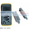
NASGQ Series Digital Display Clamp-on Phase Meter
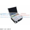
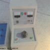
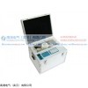
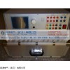
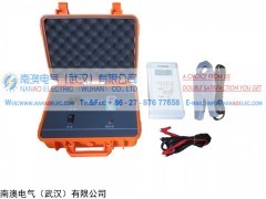
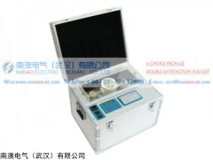
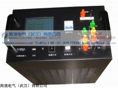
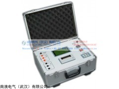
南澳电气NASGQ数字双钳相位伏安表
产品简介
南澳电气NASGQ数字双钳相位伏安表是专为现场测量电压、电流及相位而设计的一种、位、手持式、双通道输入测量仪表。NASGQ数字双钳相位伏安表可以很方便地在现场测量U-U、I-I及U-I之间的相位,判别感性、容性电路及三相电压的相序,检测变压器的接线组别,测试二次回路和母差保护系统,读出差动保护各组CT之间的相位关系,检查电度表的接线正确与否等。采用钳形电流互感器转换方式输入被测电流,因而测量时无需断开被测线路。测量U1-U2之间相位时,两输入回路完全缘隔离,因此完全避免了可能出现的误接线造成的被测线路短路、以致烧毁测量仪表。显示器采用了高反差液晶显示屏,字高达25mm,屏幕角度可自由转换约70°,以获得视觉效果。
南澳电气NASGQ数字双钳相位伏安表外壳采用工程缘材料,另配橡皮防振保护套,安全、可靠。
南澳电气NASGQ数字双钳相位伏安表产品别名
相位表,,双钳相位伏安表,钳形相位表,钳形相位伏安表,数字双钳相位表,数字式双钳相位表,低压伏安相位检测表,手持式数字双钳相位伏安表,双钳式数字相位表,双钳数字式相位表,双钳式伏安相位表,双钳伏安相位表,数显双钳相位表
南澳电气NASGQ数字双钳相位伏安表产品特性
1、不需拆母线, 一键全自动测量, 精度高, 稳定性好, 技术
2、量程自动转换, 大屏幕液晶显示, 汉字菜单操作提示, 可储存和打印数据
1、工作条件
1、环境温度:(23±5)℃
2、环境湿度:(45~75)% RH
3、被测信号波形:正弦波、β=0.02
4、被测信号频率:(50±0.2)Hz
5、被测载流导线在钳口中的位置:任意
6、测量相位时被测信号幅值范围:100~220V、0.~1.5
7、外参比频率电磁场干扰:应避免
2、 基本误差限
|
项 目 |
NASGQB |
NASGQE |
|||||
|
交流电压测量误差 |
量 限 |
20V |
200V |
500V |
20V |
200V |
500V |
|
分 辨 率 |
0.01 |
0.1 |
1 |
0.01 |
0.1 |
1 |
|
|
基本误差限 |
±(1.2%RD+2) |
±(1.0%RD+2) |
±(1.2%RD+2) |
±(0.3%读数+0.2%量程) |
|||
|
输入阻抗 |
各量限均为2MΩ |
各量限均为2MΩ相位测量时,电压端输入阻抗>500KΩ |
|||||
|
交流电流测量误差 |
量 限 |
200mA |
2A |
10A |
200mA |
2A |
10A |
|
分 辨 率 |
0.1mA |
1mA |
10mA |
0.1mA |
1mA |
10mA |
|
|
基本误差限 |
±(1.0%RD+2) |
±(0.3%读数+0.2%量程) |
|||||
|
工频相位测量误差 |
范 围 |
0~360° |
|||||
|
分辨率 |
1° |
||||||
|
基本误差限 |
±3° |
±2° |
|||||
工作误差
1、额定工作条件
1、环境温度:(0~40)℃
2、环境湿度:(20~80)% RH
3、被测信号波形:正弦波、β=0.05
4、被测信号频率:(50±0.5)Hz
5、被测载流导线在钳口中的位置:任意
6、测量相位时被测信号幅值范围
测U1-U2相位时:30V~500V
测I1-I2 相位时:10mA~10.00A
测U1-I2 或 I1-U2 相位时:10V~500V、10mA~10.00A
7、外参比频率电磁场干扰:应避免
2、额定工作误差限
在1 所述额定工作条件下,各被测量的额定工作误差限不超过相应基本误差限的两倍。
其它技术特性
1、显示位数:三位半
2、采样速率:3次/秒
3、电源:单个 9V 迭层电池、电源电流小于5mA
4、重量
表体:280g
测量钳:2×200g

Product introduction
NASGQ series Digital Display Clamp-on Phase Meter is special designed for voltage, current and phase tests, it is in high-precision, low price, portable hand-held, dual-channel input measuring. It's easy to measure the phase between U-U, I-I and U-I, identify the inductive circuit ,capacitive circuit and the phase sequence of three-phase voltage, detect the wiring group of transformer, test the seco
The shell of the device is made of engineering insulating material, together with a rubber–made anti-vibration protection kits for safety and reliability.
Also called name
Phase meter, clamp phase meter, digital clamp phase meter
The Characteristics of the products
1. Withstand Voltage
Parts between voltage input terminal and meter shell, parts between the iron core of the clamp-current transformer and seco
2. Insulation Resistance
Between meter circuit and meter shell, between the two voltage input terminals:≥10MΩ
The parameters of the products
1. Intrinsic Error
1.1 Reference Operating Co
(1) Temperature: (23±5)℃
(2) Humidity: (45~75)% RH
(3) Wave forms of measured signal: sine wave β=0.02
(4) Frequency of measured signal: (50±0.2)Hz
(5) Position of Measured current carrying co
(6) Amplitude range of measured signal when measuring phase: 100~220V, 0.~1.
(7) External reference frequency electromagnetic interference: Should be avoided
1.2 The limits of intrinsic error
|
project |
NASGQB |
NASGQE |
|||||
|
Error of AC Voltage |
Measure range |
20V |
200V |
500V |
20V |
200V |
500V |
|
Resolution |
0.01 |
0.1 |
1 |
0.01 |
0.1 |
1 |
|
|
Intrinsic limits of error |
±(1.2%RD+2) |
±(1.0%RD+2) |
±(1.2%RD+2) |
±(0.3%RD+0.2% Range) |
|||
|
Input Impedance |
All the measure range is 2MΩ |
All the measure range is 2MΩ Voltage input impedance of phase testing: >500KΩ |
|||||
|
Error of AC Current |
Measure range |
200mA |
2A |
10A |
200mA |
2A |
10A |
|
Resolution |
0.1mA |
1mA |
10mA |
0.1mA |
1mA |
10mA |
|
|
limits of intrinsic error |
±(1.0%RD+2) |
±(0.3% RD +0.2% Range) |
|||||
|
Error of Power-frequency Phase |
Range |
0~360° |
|||||
|
Resolution |
1° |
||||||
|
limits of intrinsic error |
±3° |
±2° |
|||||
2. Operating error
2.1 Rated Operating Co
(1) Temperature (0~40)℃
(2) Humidity: (20~80)% RH
(3) Wave forms of measured signal: sine wave β=0.05
(4) Frequency of measured signal: (50±0.5)Hz
(5) Position of Measured current carrying co
(6) Amplitude range of measured signal when measuring phase,
Phase U1-U2: 30V~500V
Phase I1-I2: 10mA~10.00A
Phase U1-I2 or I1-U2: 10V~500V, 10mA~10.00A
(7) External reference frequency electromagnetic interference: should be avoided
2.2 Limits of rated operating error
Under the co
3. Other technical parameters:
(1) Display: three and half digital
(2) Sampling rate: 3 times/ seco
(3) Power supply: single laminated batteries with 9V, the current of power supply is less than 5 mA.
(4)Dimension:
The size of the shell of meter: 192mm×95mm×55mm
The size of the shell of clamp: 140mm×42mm×20mm
The size of jaws: Φ7mm×9mm
(5)Weight:
The weight of meter: 280g
The weight of clamp: 2×200g
(6)the co
Temperature: -10℃~ 50℃
 免责声明:以上所展示的[NASGQ 双钳相位伏安表]信息由会员[南澳电气(武汉)有限公司]自行提供,内容的真实性、准确性和合法性由发布会员负责。
网站首页 | 最新产品 | 关于我们 | 联系方式 | 网站地图 | 网站留言 | 广告服务 | 浙ICP备10048950号-1
服务热线:(0571) 81021182 | 传真:(0571)81021183 | 邮箱:info#yi7.com (请用"@"替换"#")
客服热线:0571-85107279 展会合作:0571-85107279 友情连接:
©2010-2020 仪器交易网 All Rights Reserved